Autonomous Scleral Trocar Insertion
Perceive, plan, insert: enabling the Steady-Hand Eye Robot to autonomously perform the critical first step of a vitrectomy.
2nd place poster at Computer Integrated Surgery Poster Symposium
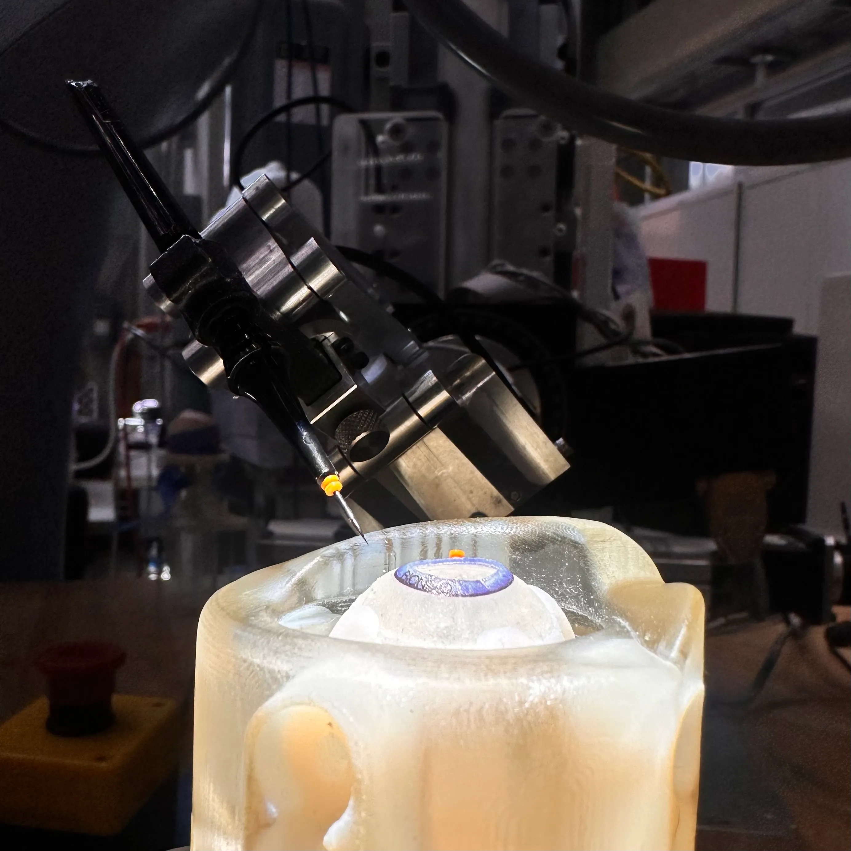
From January 2026 to May 2026, I led a research project to investigate and build a vision-guided system for autonomous trocar insertion on the Steady-Hand Eye Robot.
I recruited three teammates: Justin Wang, Luiza Brunelli, and Tianyou Liu. The project was mentored by Tianle Wu and Dr. Iulian Iordachita. Along with high-level planning and integrating each person’s contributions, I designed the registration chain and the microscope stereo depth camera, and fine-tuned and trained the segmentation model. A special thank you to teammate Justin Wang, a close friend who was brought in last-minute to help with model development so we could meet our deliverables.
Motivation & Impact
Every vitrectomy starts by placing trocars: small hollow cannulas pushed through the sclera, the white wall of the eye, that every instrument in the surgery goes in through. More than 225,000 vitrectomies are performed each year in the US alone. Each trocar has to land 3 to 4 mm behind the limbus, where the cornea meets the sclera, so it enters through the pars plana, a narrow safe band between the lens and the retina. It also has to follow the oblique technique, entering at 30° and then turning to 90° so the wound seals itself. By hand, that precision is limited by tremor (about 180 µm on average) and depends heavily on the surgeon’s experience.
Robots already help in eye surgery, but none of them make this first cut. The Steady-Hand Eye Robot (SHER) at Johns Hopkins removes tremor, but it is cooperative: it only moves when the surgeon moves it. Preceyes, ColibriDoc and recent 3D Gaussian Splatting work all assume the trocars are already placed, so nobody automates the first trocar. Our goal was a vision-guided SHER that finds a safe insertion site on the sclera and performs the oblique insertion on its own.
Approach
We split the work into two phases. Phase 1, registration, gets every camera and the robot to agree on where things are. Phase 2, perception and control, uses that to find the insertion site and move the tool. The original goal was full autonomy: drive the robot from a resting position down to the eye and insert.
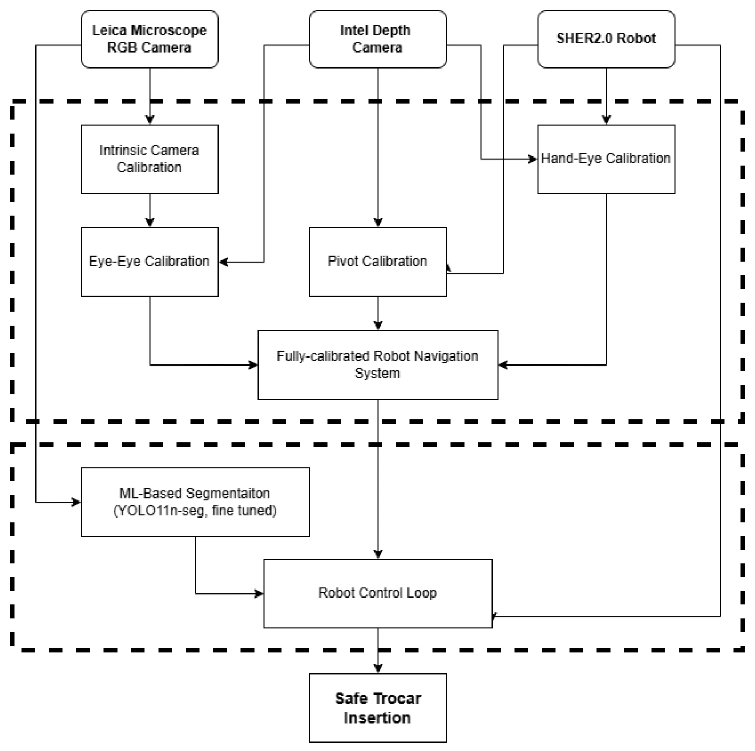
Phase 1: Registration
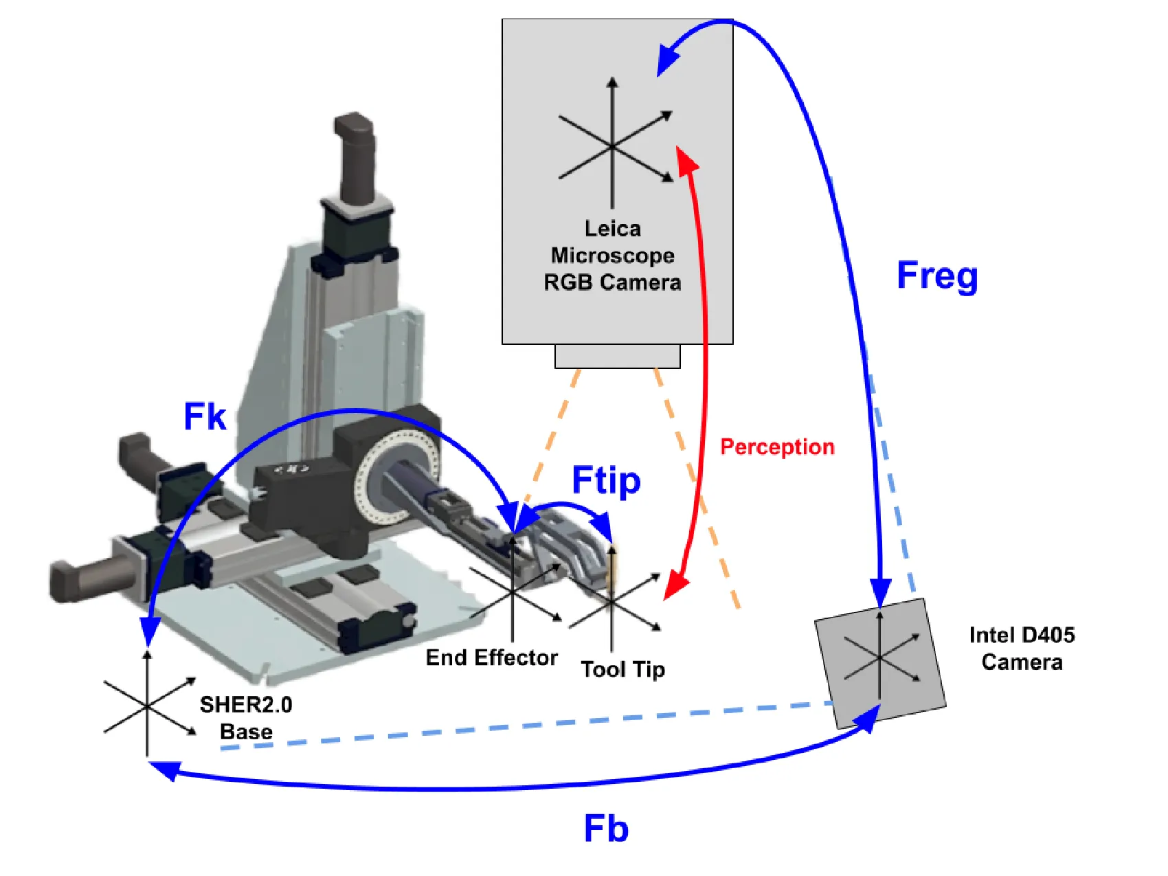
The chain has three calibrated links: F_reg between the microscope and the depth camera, F_b between the depth camera and the robot base, and F_tip between the robot’s end effector and the trocar tip. The robot’s known forward kinematics F_k connect the base to the end effector, and intrinsic calibration of each camera is the groundwork under all of it. Errors add up along a chain, so every link had to be sub-millimeter.
Intrinsics came first, all calibrated through the Leica’s optics. The Leica RGB camera reached a reprojection error of 0.904 px over 25 frames. The two FLIR stereo cameras were calibrated too, and their focal lengths came out about 14% apart because they sat on mounting tubes of different lengths.
Link 1: Microscope <-> depth camera, F_reg
This link solves F_reg, the transform between the Leica microscope camera and the Intel D405 depth camera.
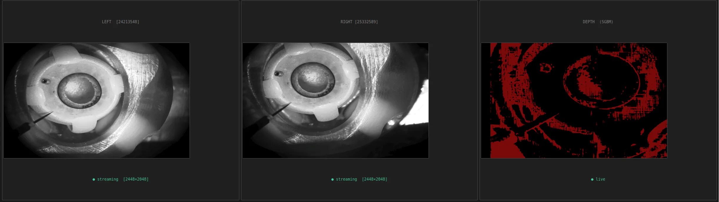
The plan. My first design gave the microscope its own depth. I mounted two FLIR Blackfly S cameras behind the Leica’s beam splitter as a hardware-synchronized stereo pair, aiming for sub-millimeter depth through the microscope’s optics, and bridged all four cameras (both FLIRs, the Leica RGB camera and the D405) into ROS. Stereo extrinsic calibration ran over 71 synchronized image pairs.
Why it couldn’t work. The disparity map came back “binary,” just noise, and working through the numbers showed why. The Leica’s 21.8× magnification pushes the effective focal length to about 43,700 px. At a 400 mm working distance that means a true disparity of about 23,000 px, 9.4 times the width of the 2,448 px sensor. A point in the left image lands entirely outside the right one, so SGBM has nothing to match and can only return noise. This was a flaw in the architecture, not a tuning problem. The 14% focal-length mismatch made it worse by corrupting the rectification.
The pivot: eye-eye calibration. The microscope can’t measure depth, but the D405 can, so I registered the two cameras directly. The target is a composite: a ChArUco 6×6 board with 4 mm squares for the Leica’s narrow, high-magnification view, plus an AprilTag 36h11 pattern for the D405’s wide view, printed on one rigid sheet. Because both patterns sit on the same flat print, the offset between them is known exactly, with no caliper measurement error.
PnP on the ChArUco corners gives leica_F_board, and PnP on the AprilTag corners gives d405_F_board. Both share the board as a reference, so F_reg = leica_F_board · d405_F_board⁻¹ comes from a single snapshot.
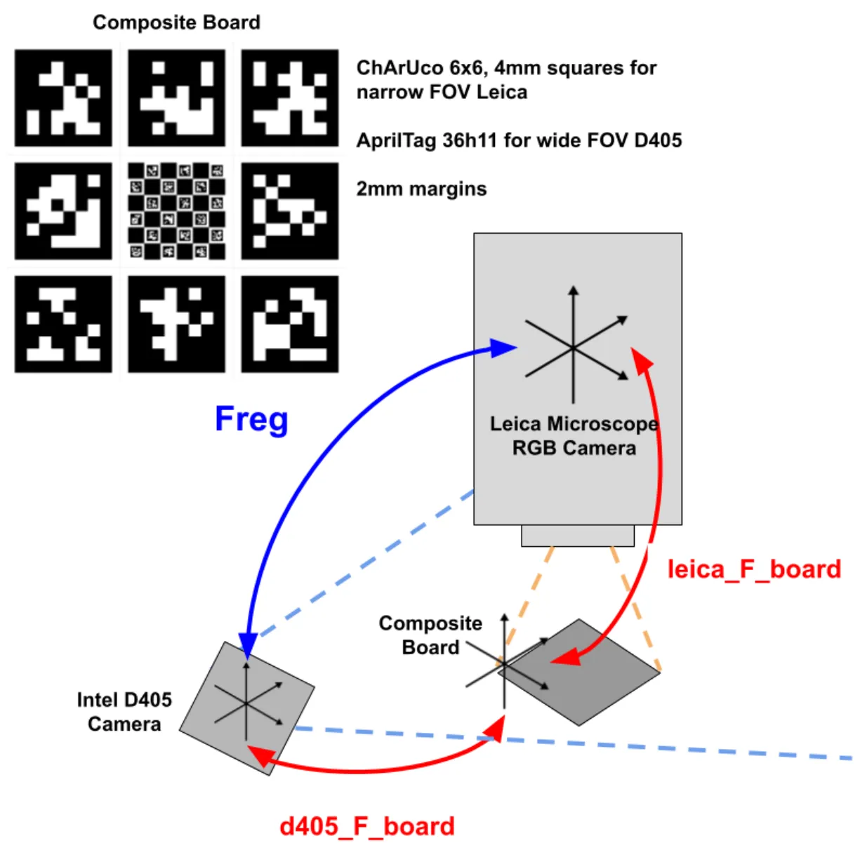
The Leica is shared between research groups and gets moved between sessions, so I built a one-click GUI that lets anyone re-register at the start of a session. Across 172 image pairs, the registration held to a mean reprojection error of 0.05 mm and 0.02°.
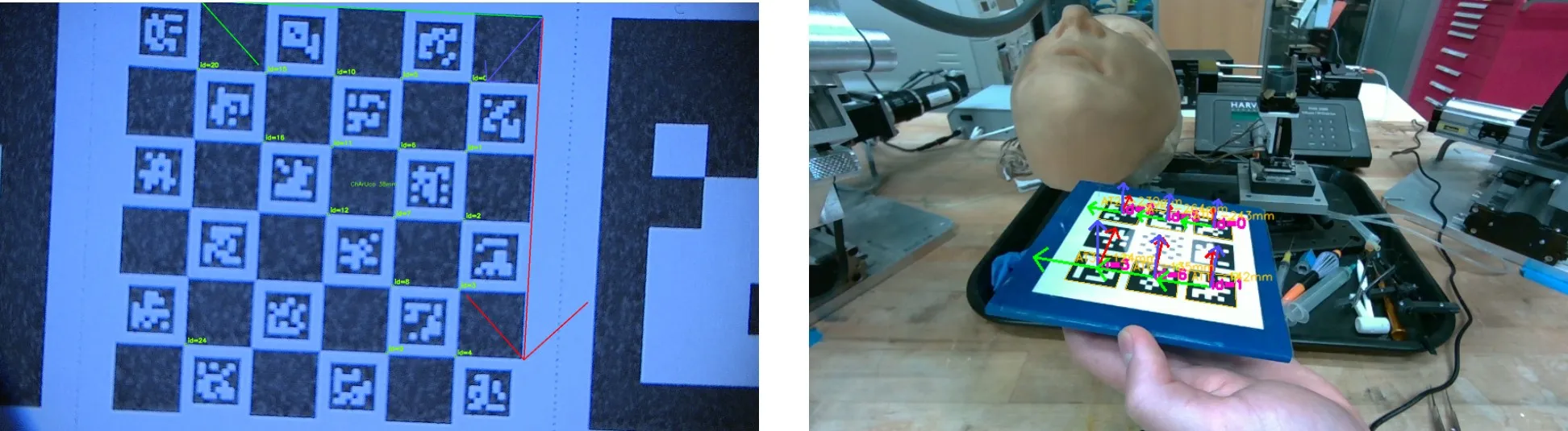
Link 2: Depth camera <-> robot, F_b
This link solves F_b, the transform between the D405 and the SHER 2.0 base, through hand-eye calibration (AY = XB) using calibration code provided by our mentor Tianle Wu. SHER 2.0 moved through a 25-pose trajectory with more than 5° of pitch and roll variation, so the solver wasn’t working from coplanar or weakly constrained motion. On an independent validation set, the mean error was 4.74 mm and 0.75°, with a maximum of 8.69 mm.
The error also depended on where the robot was working. About 55 mm away from the calibration zone it grew to roughly 12 mm, likely from gravity deflection and joint backlash, so the calibration has to be run locally, directly over the insertion site.
Link 3: Robot <-> tool tip, F_tip
This link solves F_tip, the offset from SHER’s end effector to the trocar tip, through pivot calibration, which Luiza ran. The offset measured about 40 mm, and it was validated by setting the tip in a 3D-printed divot and jogging the robot through 10 poses around it. The result was 4.51 mm RMSE (6.47 mm max) against a target of under 1 mm. The likely causes were a tip that didn’t sit perfectly on the end effector’s z-axis, noise from jogging the robot by hand, and uncertainty in the initial measurement.
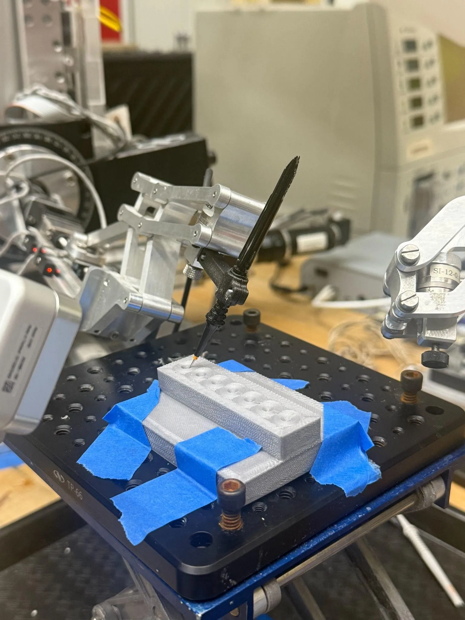
Registration Chain Results
| Calibration | Solves | n | Mean error |
|---|---|---|---|
| Camera intrinsic | Leica RGB | 25 | 0.904 px reprojection |
| Hand-eye | F_b |
17 | 4.74 mm, 0.75° |
| Eye-eye | F_reg |
172 | 0.05 mm, 0.02° |
| Pivot | F_tip |
10 | 4.51 mm RMSE |
The camera-to-camera side is solid, well under 0.1 mm. The robot side is around 4.5 mm, more than the 3 to 4 mm band the trocar has to land in, so the robot can’t be trusted to navigate to the eye on global coordinates alone, and that set up Phase 2.
Phase 2: Perception and control
Vision finds where to insert, physical contact supplies the depth, and the robot does the insertion in its own local frame.
Perception
Justin and I fine-tuned a YOLO11n-seg model (Jocher & Qiu, Ultralytics YOLO11, 2024) to segment the limbus, trocars, cannula and tool tip. This is the model deployed live on the microscope.
I annotated 358 images, 148 of ex-vivo porcine eyes and 210 of a dry-eye phantom, split 80/20 for training and validation. I deliberately varied the scenes: empty frames, zero to two trocars and tools, and fingers or other objects blocking the view, so the model wouldn’t overfit to one setup.
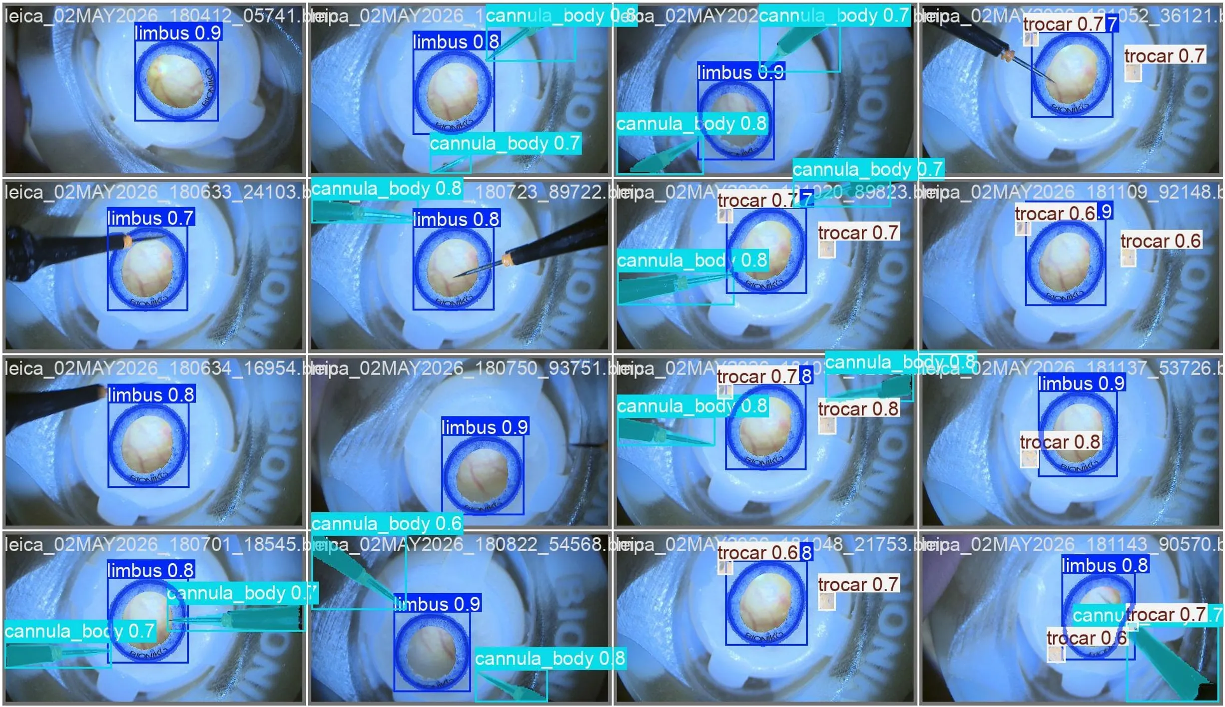
The limbus doubles as a built-in ruler. It is 11.7 ± 0.25 mm across, so once it’s segmented it sets the image scale, and a circle 4 mm behind it can be drawn straight onto the image as the insertion target, with no depth needed.
On the phantom the model reached mAP@50 of 0.995 and mAP@50:95 of 0.597. Porcine eyes are harder, with specular tissue, irregular globe geometry and variable lighting, and there it reached 0.795 and 0.375. It runs live on the Leica feed at 13.4 FPS, and at 2.84M parameters it is small enough for operating-room hardware that can’t be assumed to have a high-end GPU.
Visual servoing
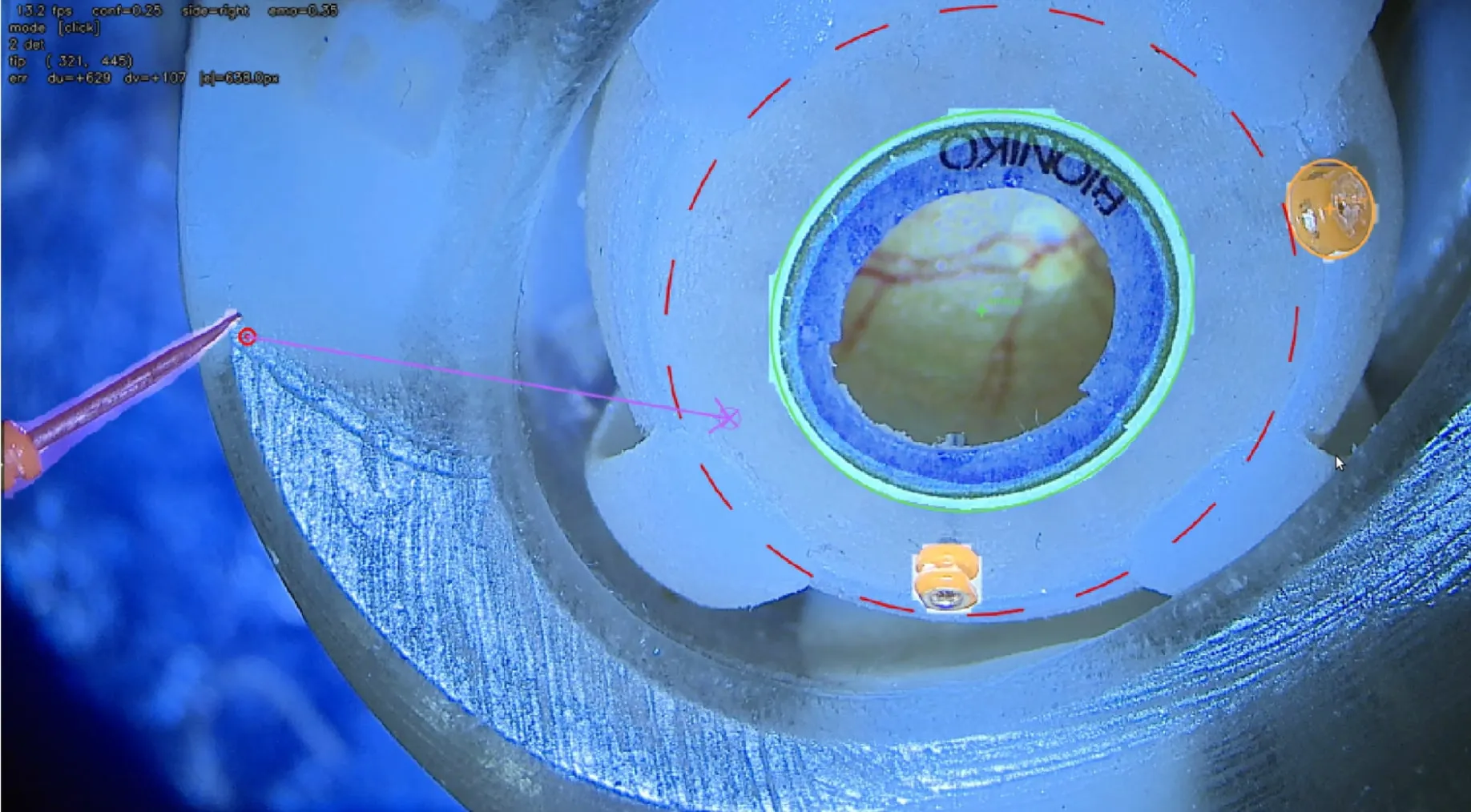
The live overlay ties the segmentation to the tool. It marks the tool tip with a red target and the selected insertion point on the 4 mm circle, draws the vector between them, and shows the live pixel error between the two as (du, dv).
Depth comes from contact. SHER is jogged until the trocar touches the eye at that site, and a ROS node locks that contact point as the remote center of motion (RCM).
Insertion
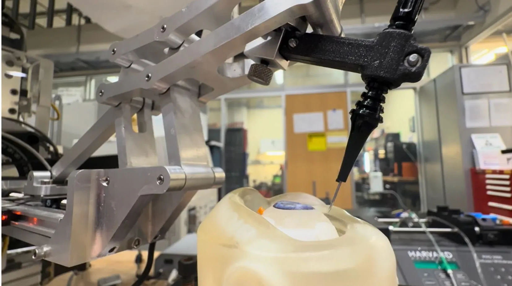
With the RCM locked, SHER runs the bi-planar oblique insertion on its own, a sequence Luiza wrote and tested. It pitches while pivoting about the tip so the sclera isn’t torn, tunnels along the tool axis, sets a new RCM inside the sclera, straightens back to perpendicular around it, plunges into the vitreous, then retracts and leaves the cannula seated.
Because of the F_b and F_tip errors, we ran it on the phantom at demonstration scale (a 20° tilt, a 4 mm tunnel and a 5 mm plunge) so the motion would be clear to see. The robot held its virtual pivot through every change in orientation.
Next Steps
The biggest limit is data. 358 images aren’t enough, which shows in the 0.20 drop in mAP@50 from phantom to porcine eyes; more globe orientations, lighting and tool setups come first.
The F_b and F_tip errors are limits of a single semester, not hard ceilings. Calibrating locally over the insertion site and a rigid machined tool mount should bring them inside the 3 to 4 mm tolerance. Removing the manual docking step entirely will need true sub-millimeter depth, most likely from OCT.
Autonomous trocar insertion works as a chain of separately validated pieces, and this project mapped exactly where the current hardware breaks.